- #5 pin relay wiring diagram how to
- #5 pin relay wiring diagram install
- #5 pin relay wiring diagram full
- #5 pin relay wiring diagram series
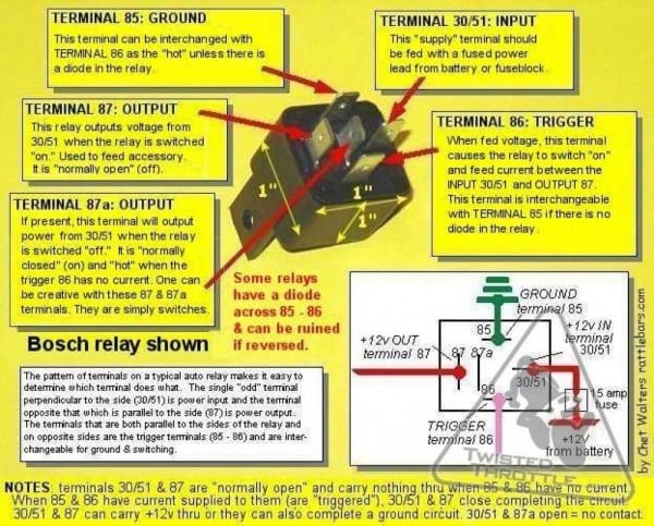
One wrong connection can result in disrupting your fog lights which of course you won’t want! You can use that to connect the fog lights but do take great care in connecting the right path to the right location. The below figure shows the wiring diagram for fog light without a relay. The above process briefly explains how we can wire a relay for fog lights. And terminal number 87 is connected to one end of the fog light and another end of the fog light is grounded.īoth circuits provide the positive output to the fog light but the way they actually operate is what differentiates both of them. Terminal 86 of the relay connects to the one end of the switch which is then grounded. In this switch having a negative terminal, terminal number 85 is wired to the 12 V power source with the help of a fuse. The second circuit is meant for a fog switch that has negative output. Once we activate the relay, the voltage is fed to the fog lights and currents start flowing. In this wiring arrangement, whenever we close the relay, a positive output is applied to the relay coil which we already connected to the ground. The other side of the switch goes to terminal 86 of the relay and terminal 85 of the relay is grounded. Power through the fuse goes through the fuse to one side of the switch connected with the fog lights. The only difference is in the activation of the relay. Similarly, the same connections are followed in the second circuit. The other side of the switch with the help of terminal 87 is connected to the first terminal of the fog light while another side of the fog light is grounded. Now, power flows from the power through the fuse to terminal 30 of the relay. A point to consider with attention is that we will always use fuse twice to the current rating of the circuit. In the left portion of the circuit, we can see the power feeding the 12V source. However, do note that we can use either one of the circuits in the wiring of the fog lights. In the fog light relay wiring diagram shown above, we can see two separate circuits which include the positive trigger circuit and negative trigger circuit that are used to wire fog lights. These two methods are explained below with the help of a fog light wiring diagram. So, basically, two methods are used to connect fog lights that can be described as positive or negative triggers.
#5 pin relay wiring diagram full
This is the area which most people neglect and can’t make full use of the fog lights.

Wiring the fog lights properly is the basic requirement to achieve the best functionality.
#5 pin relay wiring diagram how to
So, if you don’t know how to wire a relay for fog lights then this article is for you.
#5 pin relay wiring diagram install
Thus, we must install fog lights and install them correctly to avoid any serious failure at a hard time.

The added fogs make things worse as the normal high beam headlights cause glare in doggy weather which makes it harder to see. One can only know their importance when they don’t get turn-on on a dark winter night.

Regular headlights that we use in our cars give us great convenience by illuminating the roads during nighttime. Follow each step carefully to achieve the best results. In no way does claim ownership or responsibility for such items, and you should seek legal consent for any use of such materials from its owner.In this article, we’ll discuss the process to wire a relay for fog lights. Wiring Diagram For Ezgo Electric Golf Cart |Īny content, trademark/s, or other material that might be found on the website that is not property remains the copyright of its respective owner/s. Nest Thermostat Wiring Diagram For Combi Boiler |
#5 pin relay wiring diagram series
Wiring Diagram For Kenmore 70 Series Dryer |


 0 kommentar(er)
